


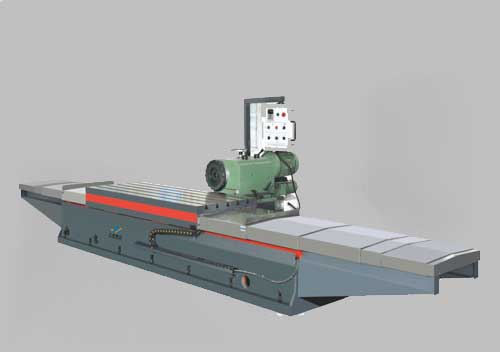
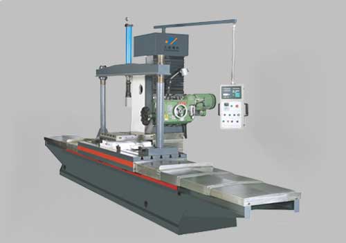
The crossbeam adopts a high-strength casting structure with a large cross-section truss structure, and has undergone multiple vibration stress relief treatments. The guide rail adopts imported heavy-duty linear rolling guide rail, which has low high-speed vibration, no crawling at low speeds, and excellent servo driving performance; At the same time, it has a high load-bearing capacity and good cutting vibration resistance.
The Z-axis guide rail pair adopts embedded steel guide rails and rolling blocks to achieve the up and down movement of the square slider. The slider and gearbox adopt a separate structure, which prevents the heat generated in the gearbox from being transmitted to the slider.
The key large castings are all made of high-strength cast iron materials and resin technology. The "rice shaped" rib plate arrangement is used to improve the stiffness and strength of the bed, and advanced finite element analysis is used for auxiliary design to ensure the reliability and stability of the product.
The machine tool can be equipped with tool magazine, right angle iron head, universal iron head, extended gun head, etc. It can also be equipped with CNC flat rotary disc according to the machining requirements of the parts, providing customers with a complete machining solution.
Specification parameters | ||||||
staging | DTK-30 | DTK-35 | DTK-40 | DTK-45 | DTK-50 | DTK-55 |
wide(mm) | 3000 | 3500 | 4000 | 4500 | 5000 | 5500 |
long(mm) | 8000-50000 | 8000-50000 | 8000-50000 | 8000-50000 | 8000-50000 | 8000-50000 |
Maximum Load(T/m2) | 20 | 20 | 20 | 20 | 20 | 20 |
trip | ||||||
X-axis stroke(mm) | 8500-50500 | 8500-50500 | 8500-50500 | 8500-50500 | 8500-50500 | 8500-50500 |
Travel Y-axis (mm) | 4500 | 5000 | 5500 | 6000 | 6500 | 7000 |
Z-axis travel(mm) | 1250/1500 | 1250/1500 | 1250/1500 | 1250/1500 | 1250/1500 | 1250/1500 |
W-axis travel(mm) | 2500-400 | 2500-400 | 2500-400 | 2500-400 | 2500-400 | 2500-400 |
Maximum width of workpiece passing through(mm) | 4000 | 4500 | 5000 | 55000 | 6000 | 6500 |
main shaft | ||||||
Distance from spindle section to worktable(mm) | Design according to customer requirements | |||||
Spindle specifications | BT50 | |||||
Spindle transmission mode | Two speed gearbox | |||||
Spindle motor power(KW) | 28/38、41/56、55/78、60/84 | |||||
Spindle speed rpm | 5-1800/5-3000 | |||||
Feed Speed | ||||||
Feed Speed X/Y/Z(mm/min) | 1-8000 | 1-8000 | 1-8000 | 1-8000 | 1-8000 | 1-8000 |
Fast moving speedX/Y/Z(m/min) | 10 | 10 | 10 | 10 | 10 | 10 |
Fast moving speedW(m/min) | 2 | 2 | 2 | 2 | 2 | 2 |
Feed rate W-axis(m/min) | 2 | 2 | 2 | 2 | 2 | 2 |
positioning accuracy | ||||||
positioning accuracy X/Y/Z | 0.02/1000 | 0.02/1000 | 0.02/1000 | 0.02/1000 | 0.02/1000 | 0.02/1000 |
repeatabilityX/Y/Z | 0.01/1000 | 0.01/1000 | 0.01/1000 | 0.01/1000 | 0.01/1000 | 0.01/1000 |
other | ||||||
Vertical slider section | 500X500/650X650 | |||||
Numerical Control System | SIEMENS 840Dsl(Other CNC systems can be selected according to customer needs) | |||||
This model can be customized according to customer needs, and specifications and models are subject to change without prior notice.

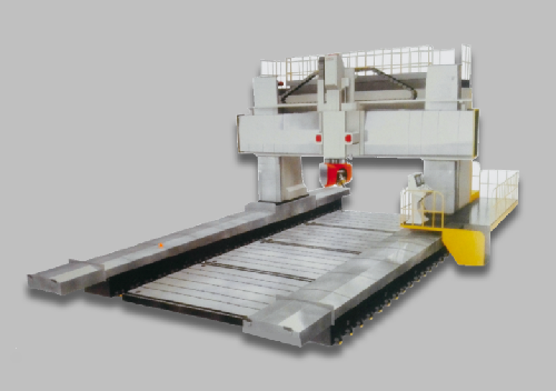
DTK-55 Moving Beam Gantry Mobile Machining Center
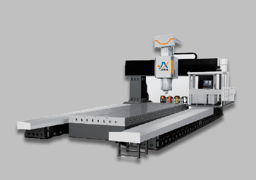
Dynamic Column CNC Gantry Boring Milling Machine
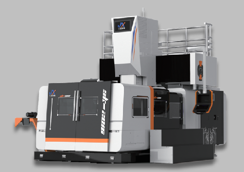
XTK-2016 CNC Gantry Machining Center
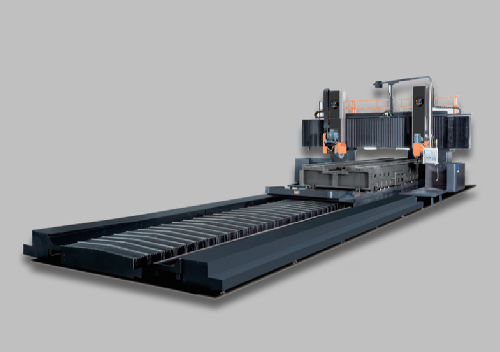
MTK-8035 CNC Gantry Guide Rail Grinder
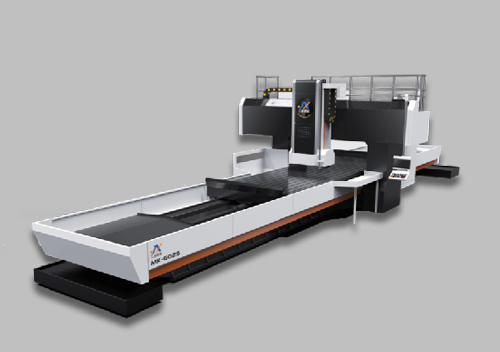
MK-6025 Longmen Surface Grinder
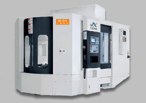
WL-1814 Machining Center
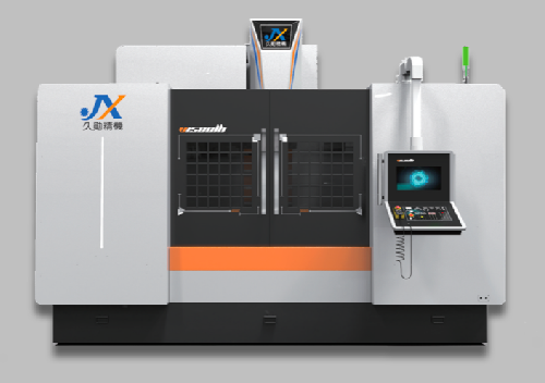
VMC-1580 Machining Center
Fixed Beam Gantry Milling Machine
Fixed Milling Machine
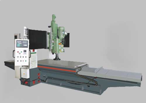
Elevating Milling Machine

0516-86605398
13812885398@163.com
www.jsjiuxun.com
High tech Industrial Development Zone, Pizhou City, Jiangsu Province